
DUAL RING MODULATOR MODEL 111

Buchla Associates model, photo credit to Switched On
The Model 111 Dual Ring Modulator is Buchla’s take on the classic modulation circuit made famous by many experimental musicians and sound designers of the 50s and 60s. A modular system would not be complete without one, and the effect falls in line with Don’s preferred methods of waveform mangling instead of the East Coast approach of sound coloration through the use of filters.
There are two versions of the Ring Modulator, and both circuits are drastically different.
CARRIER AND MODULATOR
Before we get into the differences between the two Buchla ring modulators, it’s important to talk about ring modulation and go over some of the basics. Like many modulation effects in the world of synthesis, ring modulation has its roots in radio and telephony, it was through the practice of experimentation that it was adopted by composers.
The ring modulator was invented in the 1930s, as a means of carrying multiple audio signals over one common connection, utilizing a method called Frequency Division Multiplexing. A multitude of signals would be spread across multiple bands using a local oscillator as a carrier and then the baseband frequency (or desired signal) would be filtered out at the other end by the modulator. This invention alone cut down on the number of wires and cables that connected the world together, allowing multiplexing to do all the heavy lifting over long distances.
The following image of the first patented ring modulator comes from Frank A. Cowan, who improved a previous design to utilize a much smaller part count. This is an example of the classic “diode-ring” modulator.
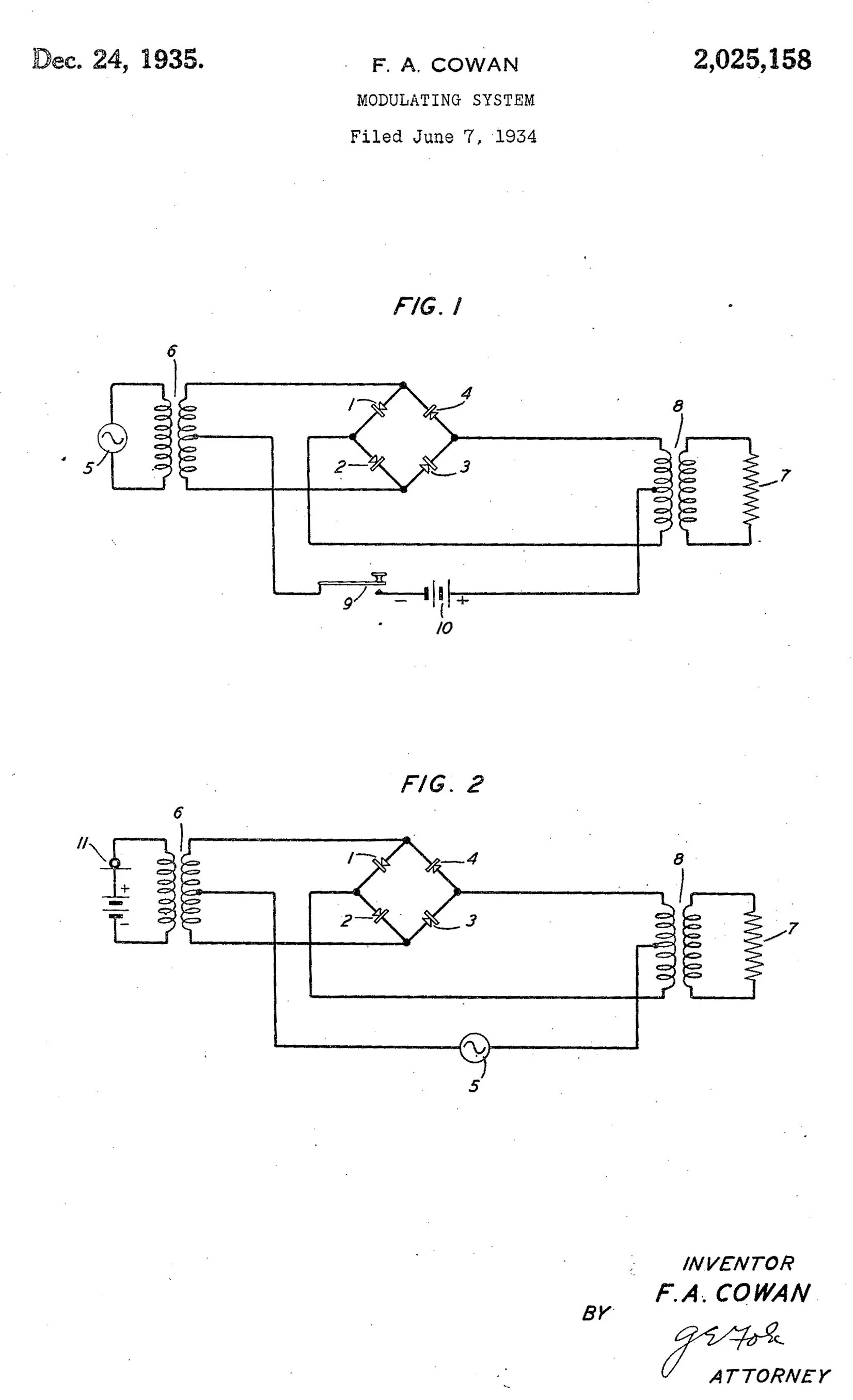
First patented ring modulator, from Frank Cowan.
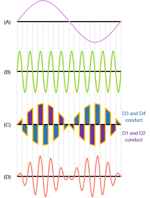
Condensed version of how a ring modulator will use diodes to multiply two signals.
DIODE RING MODULATION
The name “Ring Modulator” has a very literal etymology. Rather than describing the ringing or metallic sounds of ring modulated sound sources, the name is a nod to the actual construction of the electronic circuit. The first ringmod circuits utilized a series of four diodes arranged in a “ring” shape.
The “carrier” waveform that is input into the module is multiplied by the “modulator” to output both the sum and the difference of the two waveforms. To do this, the diodes are arranged to conduct in two separate pairs, and at alternating polarities, when the audio signal goes positive or negative. In this example, A is the carrier, and B is the modulator. The two frequencies are multiplied (C) and the resulting output (D) represents the sum AND difference of the two waveforms.
The earliest example of an instrument utilizing a ring modulator is the Melochord, introduced by Harald Bode in 1947. This wouldn’t be the last time that Bode skated on the cutting edge of electronic design, later pioneering modules such as his Frequency Shifter.
Since Bode was very active in the early 60s (especially as chairman of the AES convention), many designers borrowed or collaborated on his designs. Bode’s ring modulator was adopted by Robert Moog and has some similarities in architecture to Don’s first San Francisco Tape Music Center design.

Bode and the Melochord
TRANSISTOR MULTIPLIERS
Ring modulation has evolved over the years to eliminate the cumbersome transformers and improve carrier cancellation, which reduces the amount of carrier signal that leaks into the output.
In 1968, Barrie Gilbert (a Tektronix engineer) came up with a four quadrant multiplier utilizing differential amplifiers (later dubbed Gilbert Cells) that would easily multiply bipolar signals with high precision, without the need for diode rings. This is called the Gilbert Four-Quadrant Multiplier. Which indirectly leads us to the Model 111 that we all know and love.

The Gilbert Four Quadrant Multiplier and a section of the CBS 111
A TALE OF TWO RING MODULATORS
Before the project started, we were under the assumption like many that the 111 is the 111, and that the CBS version was the standard issue Buchla module. But of course, in true MEMS fashion, we had to mine the depths.

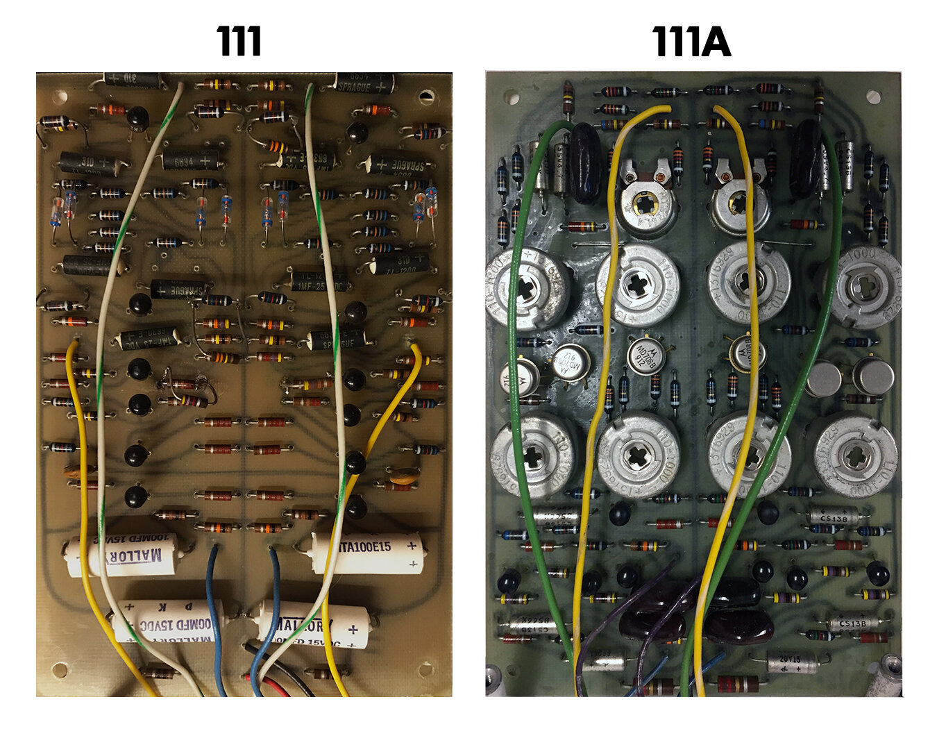
Closer detail of the San Francisco Tape Music Center 111 and the CBS 111Aa. The solder joints here are so perfect that you can see Lon’s reflection in the solder as he helped document the Stearns system.
There are early versions of the San Francisco Tape Music Center 111s which actually took advantage of panel real estate and sported four control knobs. These were labeled NULL ADJUSTMENTS. The null adjustment is in reality what you would call a “carrier control” trimmer. This knob trims out any remaining dry carrier signal that could be leaking into the sum or differential outputs. This was made adjustable because the 111 does not have an internal carrier oscillator, so different inputs could cause bleed depending on the signal strength or frequency spectrum.
The early 111 boards had spaces for these potentiometer controls. As time moved on, Don seemed to scrap the idea of using Null Adjustment knobs and left these holes empty. Perhaps the adjustment was too narrow or produced undesirable effects with certain signals.
Regardless of controls, it’s very important to realize here that the San Francisco Tape Music Center 111 is a diode ring modulator, while the CBS 111A version is a transistor multiplier ring modulator. While this is an improvement on the design, the diode ring version sounds much grittier and pronounced, with the added benefit of zero trimmers to adjust.
111 RECONSTRUCTION
So far, MEMS has built quite a few ring modulator boards, as Frequency Shifter modules also call for this board to be added to the large stack of standoffs. Tuning and adjusting the trimmers becomes a chore. However, the San Francisco Tape Music Center 111 has been a delight to build, with zero adjustments.
Don’s change to the Gilbert cell design could be explained in many different ways (more than likely the redesign centered around the 185) but the most important explanation could just be that he was so cutting edge that he jumped on Gilbert’s idea as it was fairly revolutionary in 1968.
